

SKF Bearing Alignment for EU Conveyor Retrofits Wholesale Supplier
Most bearing failures in conveyor retrofits are blamed on product quality. The real culprit is almost always misalignment during installation.
Proper bearing alignment during EU conveyor retrofits is the single most critical factor determining service life. Misalignment — not bearing material defects or load miscalculation — causes the majority of premature failures in retrofit scenarios, where existing frames have been modified, rewelded, or thermally stressed over decades of service.
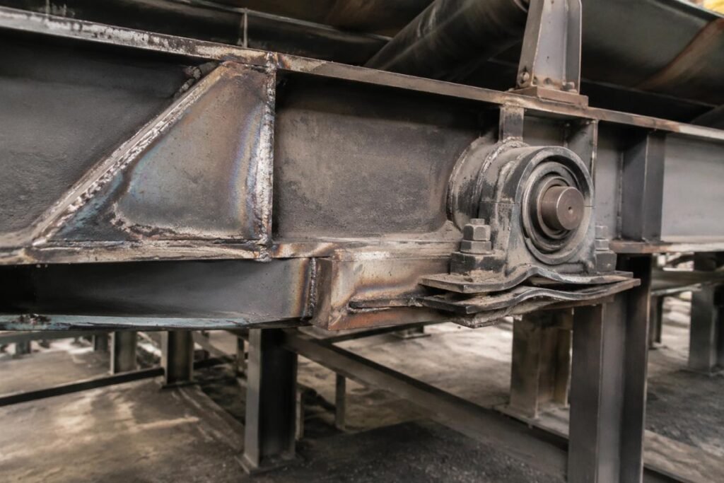
I still remember a cement plant conveyor retrofit in Riyadh where the client rewelded the entire support frame, then installed a full set of SKF spherical roller bearings we supplied. Within months, the bearings were running hot and throwing vibration alarms. The plant maintenance team was convinced they had received counterfeits. When I arrived on-site and pulled out a laser alignment tool — something they had never used during installation — the bearing seat coaxiality deviation was sitting right around the sub-millimeter range, with welding distortion completely uncorrected. The bearings were absorbing forces they were never designed to handle. That kind of scenario repeats across Middle East and EU industrial sites constantly, and it traces back to one root issue: alignment procedure was either skipped or performed with inadequate tools. [NEED_CITE: root cause distribution of premature bearing failures in conveyor applications per ISO 15243 damage classification]

Let me walk through what actually matters when you are executing a conveyor retrofit in an EU industrial facility — the tolerances, the procedure, the failure signatures, and the verification steps that separate a successful commissioning from a repeat teardown.
Why Bearing Alignment Matters More Than Bearing Quality in Retrofits?
Retrofit conditions amplify alignment risks far beyond greenfield installations, because existing structures carry decades of thermal cycling, welding modifications, and foundation settlement that new-build conveyors simply do not have.
When a conveyor system is originally installed in a controlled new-build environment, the frame is fabricated to specification, bearing seats are machined in-line, and thermal growth is calculated into the design from day one. A retrofit strips away all those advantages. The frame may have been cut and rewelded multiple times over its service life. Bearing pedestals may have been patched with shims or repositioned during previous maintenance campaigns. The foundation itself may have settled unevenly.
In one port facility retrofit I inspected in the Gulf region, a long overland conveyor had been extended during a capacity upgrade years earlier. The extension section was bolted to the original structure without compensating for differential thermal expansion across the full run. During operation, axial displacement in the sub-millimeter to low-millimeter range developed across the conveyor length, pushing bearing loads well beyond their designed axial capacity. The bearings were genuine, correctly specified, and properly lubricated. They failed anyway — because the system-level alignment was never addressed.
This is where the misconception about self-aligning bearings becomes dangerous. Many maintenance teams assume that because SKF spherical roller bearings can accommodate some angular misalignment, they will tolerate any installation error. That assumption is incorrect. These bearings have strict angular limits — typically around the half-degree mark — beyond which internal stress concentrations spike dramatically, raceway contact patterns distort, and cage guidance deteriorates. [NEED_CITE: SKF spherical roller bearing misalignment tolerance specifications from manufacturer maintenance handbook]
The practical implication is clear: self-aligning capability is a design feature for operational deflection, not a license for sloppy installation. In retrofit scenarios, where frame geometry is inherently compromised, precision alignment becomes even more important than in new installations.

What Are the SKF Alignment Tolerances for Conveyor Applications?
Understanding the actual angular, axial, and radial alignment limits for SKF spherical roller bearings is essential — because these limits are far tighter than most maintenance teams assume, and exceeding them accelerates failure mechanisms that mimic lubrication problems or material defects.
SKF publishes alignment tolerance data for their spherical roller bearing series — including the 223xx and 230xx series commonly specified in conveyor head, tail, and bend pulley positions. These tolerances define the maximum permissible deviation before internal bearing geometry is compromised. The key parameters are angular misalignment, axial displacement, and radial offset between paired bearing seats.
Angular misalignment tolerance for standard SKF spherical roller bearings typically sits around the half-degree threshold. Beyond this point, the contact pattern between rollers and raceways shifts from the designed uniform distribution to edge-loaded concentrations. This generates localized stress peaks that initiate subsurface fatigue cracks far earlier than the bearing’s calculated L10 life would predict.
Axial displacement limits vary by bearing size and series, but the underlying principle is consistent: excessive axial offset forces the bearing to accommodate thrust loads it was not designed to carry, accelerating cage wear and roller skew.
Here is a qualitative tolerance framework for conveyor retrofit alignment:
| Alignment Parameter | Acceptable Range | Risk Zone | Critical Failure Zone |
|---|---|---|---|
| Angular Misalignment | Within manufacturer specification | Approaching self-aligning limit | Beyond self-aligning capacity |
| Axial Displacement | Compensated within bearing design limits | Uncompensated thermal growth observed | Structural constraint forcing axial load |
| Radial Offset (Coaxiality) | Within machining tolerance per ISO 113 | Visible deviation without laser verification | Substantial deviation from coaxial centerline |
| Bearing Seat Fit | Standard h7/j7 per ISO 113 | Loose fit with visible fretting | Severe fit mismatch requiring sleeve repair |
[NEED_CITE: ISO 113 bearing fit tolerance specifications for shaft and housing applications]
The bearing seat machining tolerance is another area where retrofit conditions create hidden problems. Per ISO 113, standard fits for spherical roller bearing housings follow h7 or j7 tolerance classes. In a retrofit where the original pedestal has been rewelded or re-machined by a local workshop without reference to these standards, the actual fit may fall well outside specification — creating either a loose fit that allows fretting corrosion or an interference fit that eliminates internal clearance.
I have seen retrofit installations where the bearing seat bore was measured and found to be substantially oversized compared to the specified tolerance class. The bearing appeared to install correctly, but under load it shifted microscopically, generating fretting damage that mimicked raceway spalling within a short operating period.
How to Perform Laser Alignment Step-by-Step During Retrofit?
Laser-based alignment is the only reliable method for verifying bearing seat coaxiality and pulley alignment in conveyor retrofits — visual inspection and straightedge methods cannot detect deviations in the sub-millimeter range where bearing damage originates.
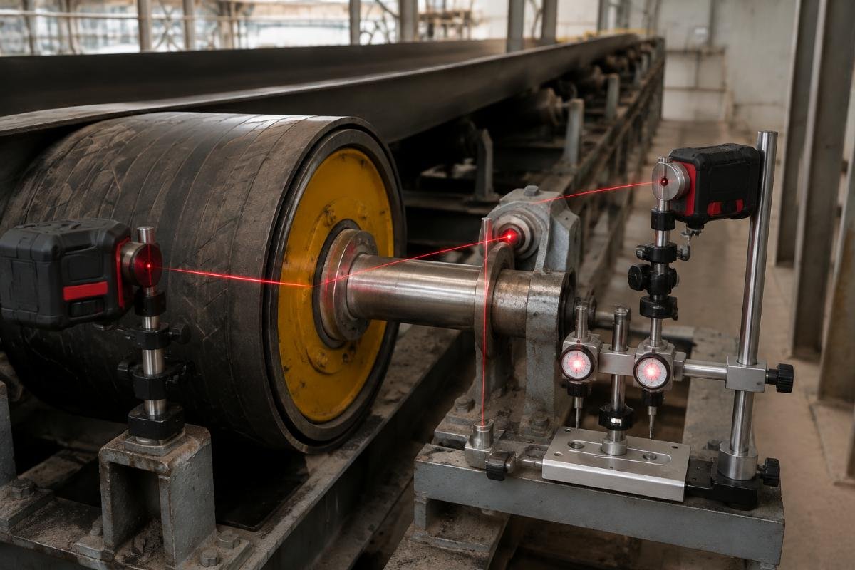
The alignment procedure for a conveyor retrofit follows a logical sequence that addresses both the bearing seats and the pulleys, since misalignment at either location propagates through the system. The process requires a rotational-offset laser alignment tool capable of measuring both angular and parallel deviation simultaneously.
Step 1: Pre-Alignment Frame Assessment
Before mounting any alignment equipment, inspect the entire conveyor frame for visible distortion, weld repairs, and foundation settlement. Document any section where the frame has been modified from its original configuration. These areas are the highest-risk points for alignment deviation and should receive priority measurement attention.
Step 2: Bearing Seat Coaxiality Verification
Mount the laser alignment tool across the bearing seat pair at each pulley position. Measure both rotational offset and parallel displacement. Record the deviation values. If any bearing seat pair shows deviation beyond the acceptable tolerance range, the seat must be re-machined or the pedestal repositioned before bearing installation proceeds. Skipping this step and attempting to compensate with shims is a temporary fix that will not survive thermal cycling.
Step 3: Pulley Alignment Check
With bearing seats confirmed within tolerance, mount the laser system across the conveyor’s head and tail pulleys. Measure angular and parallel alignment of the pulley shafts relative to the conveyor centerline. Conveyor pulley alignment directly affects belt tracking and bearing load distribution — a pulley that is angularly misaligned forces the belt to run at an angle, generating asymmetric loading on the bearings.
Step 4: Thermal Growth Compensation Calculation
For conveyor runs exceeding a moderate length, calculate the expected thermal expansion of the frame and pulley shafts across the operating temperature range. Steel expands predictably with temperature, and on a long conveyor, the cumulative axial displacement can reach the low-millimeter range between cold installation and hot operation. The alignment procedure must account for this displacement — typically by setting the cold-state alignment to a calculated offset that brings the system into true alignment at operating temperature.
[NEED_CITE: thermal expansion compensation methodology for conveyor systems per CEMA design standards]
Step 5: Post-Alignment Verification
After all adjustments are complete, re-run the full laser alignment measurement sequence to confirm that all parameters fall within specification. Document the final alignment values as the commissioning baseline.
In a mining conveyor upgrade I reviewed, the installation team had replaced the belt and pulleys but skipped the pulley alignment check entirely. The angular misalignment at the head pulley was substantial — well beyond the half-degree threshold. Within a short operating period, the roller wear pattern on the belt showed clear asymmetric contact, and the head pulley bearings were generating elevated vibration signatures. The bearings were not defective. The alignment was never performed.
What Failure Patterns Indicate Misalignment vs. Other Issues?
Misalignment produces distinctive failure signatures that differ clearly from lubrication failure, contamination damage, or overload spalling — recognizing these patterns prevents misdiagnosis and unnecessary bearing replacement with the same root cause unresolved.
When a bearing fails due to misalignment, the damage follows predictable patterns tied to the asymmetric loading that misalignment creates. Understanding these patterns allows maintenance teams to identify the true root cause rather than attributing the failure to bearing quality.
Asymmetric Roller Wear
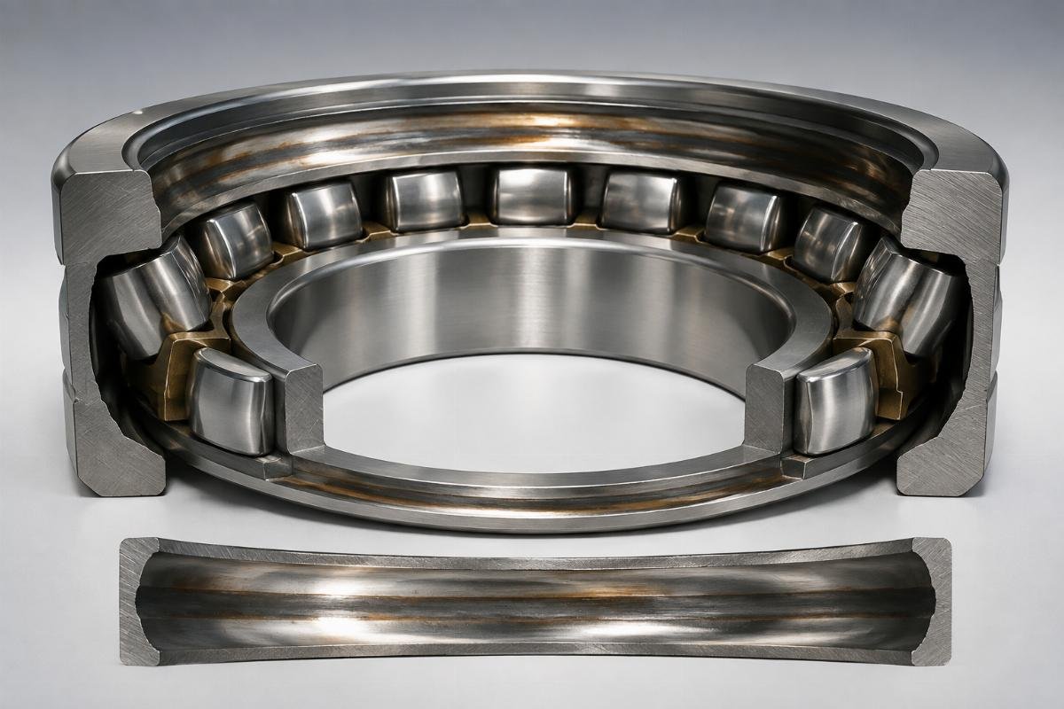
In a misaligned spherical roller bearing, the contact pattern between rollers and raceways shifts toward one end of the roller. This produces visible wear tracks that are concentrated at the roller edge rather than distributed across the full roller length. When you examine removed rollers from a misalignment failure, the wear is distinctly one-sided — a clear indicator that the bearing was operating under angular or parallel offset.
Cage Deformation and Skew
Misalignment forces rollers to skew within their pockets, generating asymmetric guidance loads on the cage. Over time, this produces visible deformation of the cage pockets — typically elongation or polishing on one side of each pocket. In advanced stages, the cage may show cracking at the pocket bridges. This damage pattern is distinct from cage failure caused by lubrication starvation, which typically produces uniform wear across all pockets.
Elevated Vibration at Specific Frequencies
Misaligned bearings generate vibration signatures at characteristic frequencies related to the shaft rotational speed and the bearing’s internal geometry. The vibration spectrum typically shows elevated amplitude at the ball pass frequency outer race and ball pass frequency inner race, with harmonics — a pattern distinguishable from the broadband vibration generated by general contamination or the discrete frequencies associated with localized raceway defects.
[NEED_CITE: vibration evaluation criteria for rotating machinery per ISO 10816 damage classification]
Raceway Contact Pattern Distortion
If you section a failed bearing from a misalignment condition, the raceway contact pattern will show clear asymmetry — the loaded zone is concentrated on one side of the raceway rather than distributed symmetrically. This is the definitive forensic indicator of misalignment, distinguishable from overload spalling (which shows symmetric contact patterns with subsurface-initiated spalls) or lubrication failure (which shows uniform surface distress across the loaded zone).
In a European steel mill conveyor retrofit, the maintenance team replaced bearings three times over a short period, each time attributing failure to a suspected batch quality issue. When I examined the removed bearings, every unit showed the same asymmetric roller wear and cage pocket elongation pattern. The bearing seats were never checked for coaxiality after the frame was modified during the retrofit. The root cause was alignment — not the bearings.
How to Verify Alignment Quality Before Commissioning?
A structured verification protocol combining vibration baseline measurement, thermal imaging, and controlled run-in monitoring is essential before signing off on a conveyor retrofit — it catches residual alignment issues that static laser measurements may miss under operating conditions.
Static laser alignment confirms geometry at ambient temperature with no load. But a conveyor in operation experiences thermal growth, belt tension loading, and material weight — all of which can shift alignment from the cold-state baseline. A proper commissioning verification protocol accounts for these operational factors.
Vibration Baseline Measurement
After the conveyor has completed its initial run-in period, perform a full vibration survey at each bearing position. Record the overall vibration velocity and analyze the frequency spectrum. Compare the readings against the ISO 10816 evaluation zones for the specific machine class. Any bearing position showing vibration amplitude approaching or exceeding the alert threshold should be flagged for re-inspection — even if the static laser alignment was within tolerance.
[NEED_CITE: ISO 10816 vibration evaluation zones for industrial machinery classification]
Thermal Imaging Spot-Check
Use an infrared thermal camera to scan all bearing positions during the first hours of operation. A properly aligned bearing will reach a stable operating temperature within a predictable range. A bearing that is running substantially hotter than its paired counterpart on the same shaft indicates residual misalignment, excessive preload, or fit interference — even if vibration readings appear acceptable.
In the Riyadh cement plant case I mentioned earlier, thermal imaging during the initial run-in would have flagged the problem immediately. The misaligned bearings were running noticeably hotter than the design baseline within the first hour of operation. But no thermal check was performed during commissioning, and the problem was only discovered when the temperature alarms triggered weeks later — by which point the bearing internal geometry had already sustained irreversible damage.
Controlled Run-In Monitoring Protocol
For critical conveyor applications, implement a structured run-in monitoring protocol during the initial operating period. Record vibration, temperature, and noise data at defined intervals — for example, at the start of each shift during the first days of operation. Plot the trends. A properly aligned and installed bearing will show stable or slightly decreasing vibration and temperature as the internal surfaces seat. A bearing with residual alignment issues will show increasing trends — a clear early warning that intervention is needed before secondary damage develops.
Documentation and Handover
Record all verification data — laser alignment values, vibration baselines, thermal images, and run-in trend charts — as part of the commissioning documentation package. This baseline serves as the reference for all future condition monitoring and provides the maintenance team with a clear picture of the as-commissioned state.

Conclusion
Alignment is the foundation of bearing service life in conveyor retrofits — no bearing specification, however robust, can compensate for installation geometry errors that force it to operate outside its design envelope.
The evidence from field experience across multiple continents is consistent: the majority of premature conveyor bearing failures in retrofit scenarios trace directly to misalignment — angular offset at bearing seats, uncompensated thermal growth across long conveyor runs, and skipped pulley alignment checks during belt replacement. The corrective actions are well-established: laser-based coaxiality verification, thermal growth compensation, structured commissioning protocols, and failure pattern recognition that distinguishes misalignment damage from other root causes. For maintenance engineers and plant managers executing EU conveyor retrofits, investing in alignment precision delivers returns that far exceed the cost of the measurement equipment and the additional installation time required.



Leave a Reply